1. Overview
A contact condition can model additional resistances at the boundary between different materials.
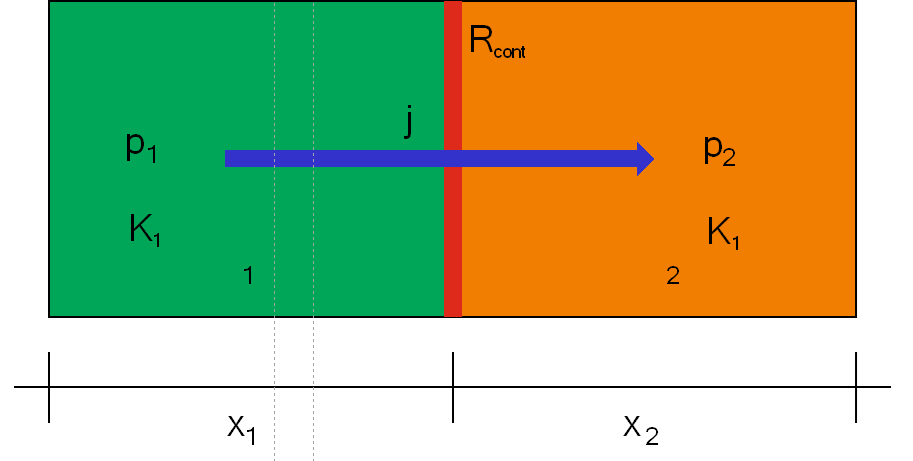
Such a resistance can be used for the following flows:
-
heat flux
-
vapor flux
-
liquid flux
-
air flux
The resistance can be constant (simple model) or depending on an other variable. This allows the modelling of a vaport retarder as contact condition. There are some limitations:
-
no thermal storage and resistance
-
no moisture storage
-
no liquid or air transport
-
no transport of any quantity lengthwise to the vapor retarder
That means the contact condition only models the vapor transport itself. Here the sd-value is used as parameter. This value can be constant or depending on surrounding relative humidity (smart vapor retarder). A dependence on flow direction and vapor pressure gradient is also possible (advanced models).
2. Vapor retarder models
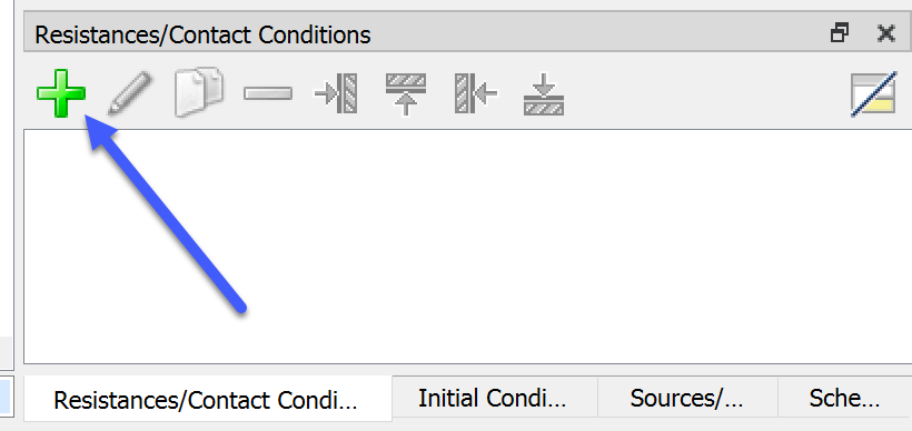
If you want to add a contact condition click on the green plus button in the contact condition section (normally right bottom in the main window)
Then the dialog for a contacht condtion will open. Here you can select kind and type of the condition. For a vapor retarder you have the following options
-
Foil (… constant vapor diffusion barrier)
-
no kinds
-
-
Foil (… moisture dependent vapor diffusion barrier)
-
resistance direction dependent
-
resistance direction independent
-
Using a contact condition instead of a real material layer has some advantages:
-
no need to discretize the very thin layer
-
less amount of volume elements
-
not too small volume elements
-
-
no need to use the material of the vapor retarder with its very small moisture storage.
Especially the very small elements in combination with a small moisture storage can create a lot of solver problems which ends up in very small time steps. Finally, the use of a contact condition can dramatically increase the computational speed.
2.1. Types
First we start with a constant vapor barrier.
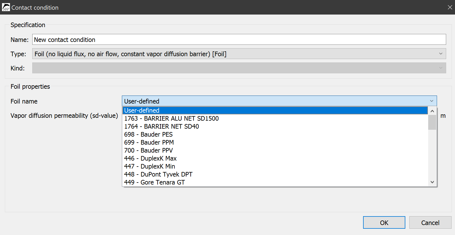
Click on the list beside 'Foil name' will open a list of all vapor barriers in the DELPHIN database. On the top of the list you can choose a user defined vapor retarder. There you can set your own sd-value. You only need to select one and give an appropriate name.
If you choose moisture dependent vapor barrier you have two kinds:
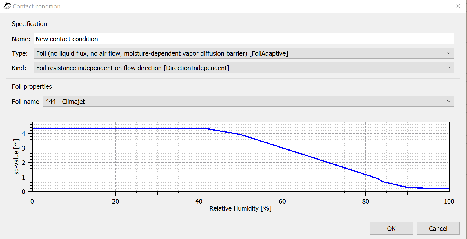
Here you can only select a vapor retarder from the list. On the bottom part of the dialog you will see a diagram with sd-value depending on surrounding realtive humidity.
If you want to add a moisture and direction dependent vapor barrier you have to choose the kind 'Foil resistance differs on flow direction'. In the current DELPHIN version we have only one possible material here.
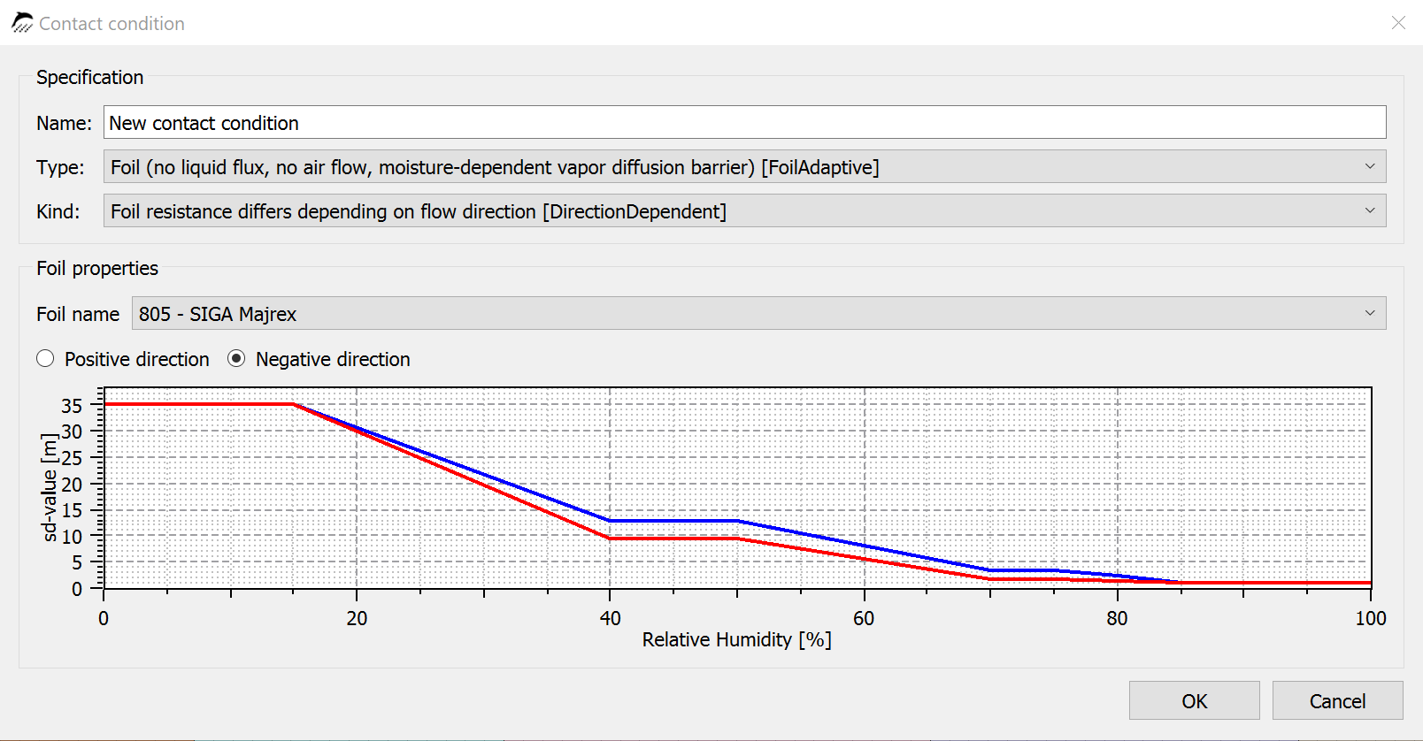
For moisture depending vapor barriers we don’t have a user defined type. If you want to add such a material you have to create a new material file which you can copy into your user material database. If you want to see how such material looks like you can open a file of an existing vapor barrier in our database with a normal text editor.
All vapor retarders in the list are part of the material database of DELPHIN. The lists will be updated only while starting DELPHIN. If you want to add a new vapor barrier you need to add a new material file to the user material database. DELPHIN will update the internal lists at the start.
After you have created your contact condition you need to assign it to the construction.
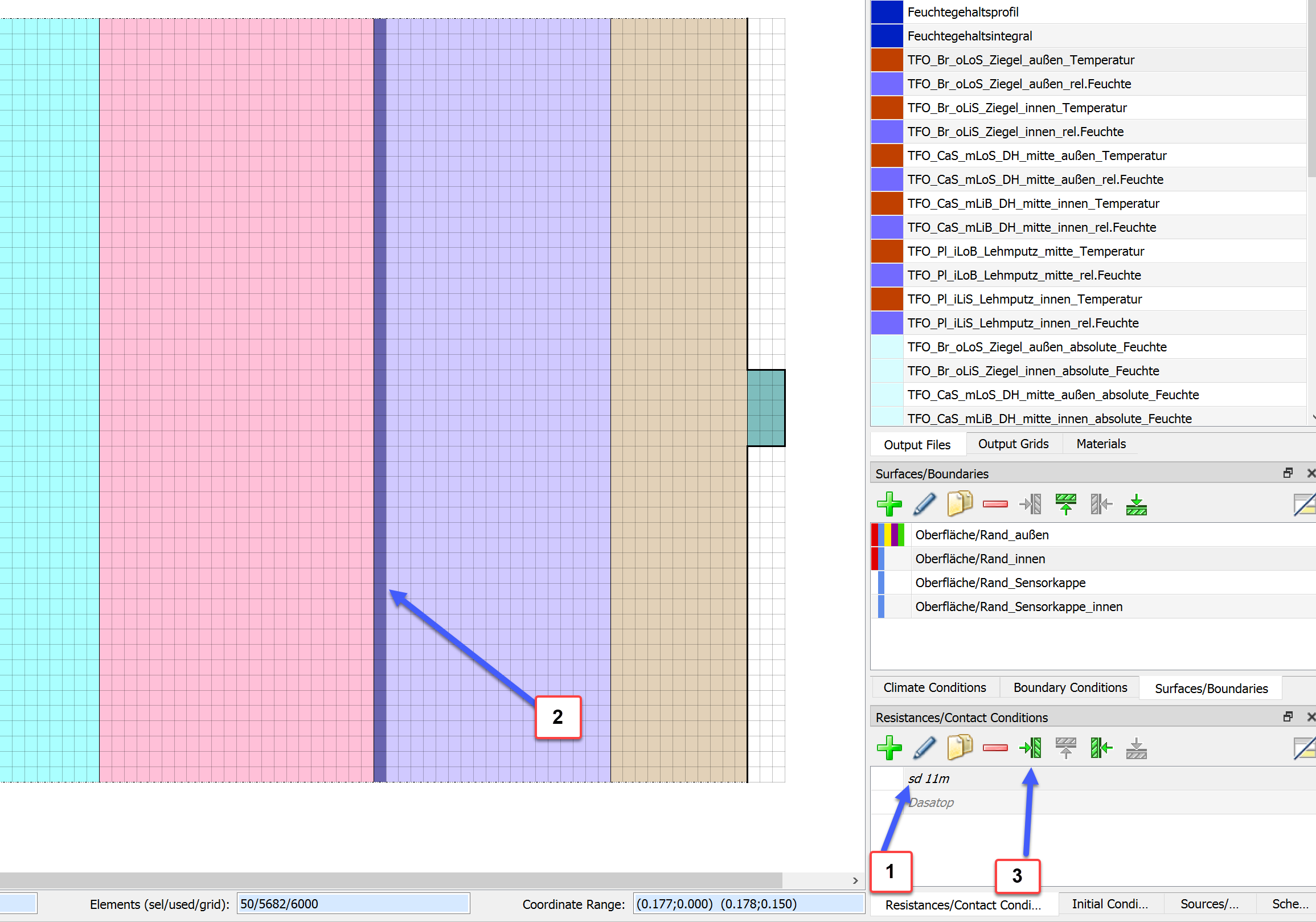
2.2. Assigning contact conditions
Because a contact condtion works at the boundary between elements you have to assign it to the side of the elements you wish.
-
Click at the contact condition you wish
-
Select elements left or right (top or bottom) of the side where you want to have the vapor barrier
-
assign it to the right side depending on your selection
Thats it.
You can assign as many contact condtion as you like but not at the same place.
3. Description in the material file
In order to define the data for a contact condition use of a vapor retarder you have to add the section VAPOR_CONTACT_RESISTANCE. Such a section consists of different parts:
-
sd-function
-
weight factor
-
scaling coefficients
In case of a direction depending sd values you can have all parts for positive and negative direction. In case of missing scaling coefficient the sd value doesn’t depend on relative humidity gradient (nearly all vapor retarder). If the weight factor is missing a default value of 0.5 (normal arithmetic average) will be used. That means the only necessary part is the sd-value function for the positive direction. In the following you will see two examples for a standard smart vapor retarder and for a vapor retarder with all effects.
Normal smart vapor retarder
[VAPOR_CONTACT_RESISTANCE]
  FUNCTION =              sd+(rh)
      0                0.15             0.2              0.4              0.5              0.7              0.75             0.8              0.85             0.9              0.95             1
      28               28               28               9.39             8.61             2.16             2.16             0.89             0.89             0.68             0.57             0.57
Smart vapor retarder with parameters for direction and gradient dependencies
[VAPOR_CONTACT_RESISTANCE]
  FUNCTION =              sd+(rh)
      0                0.15             0.4              0.5              0.7              0.75             0.8              0.85             0.9              0.99             1
      35               35               12.97            12.97            3.52             3.52             2.36             1.16             1.16             1.16             1.16
  WEIGHT_FACTOR_POS        = 0.52
  SCALING_A_POS            = 0.11795
  SCALING_B_POS            = 0.010393
  SCALING_C_POS            = 0.010393
  FUNCTION =              sd-(rh)
      0                0.15             0.4              0.5              0.7              0.75             0.8              0.85             0.9              0.99             1
      35               35               9.45             9.45             1.6              1.6              1.39             1.16             1.16             1.16             1.16
  WEIGHT_FACTOR_NEG        = 0.55
  SCALING_A_NEG            = -0.6271
  SCALING_B_NEG            = 0.042838
  SCALING_C_NEG            = 0.042838
Th complete model and the measurements are described in the following paper: